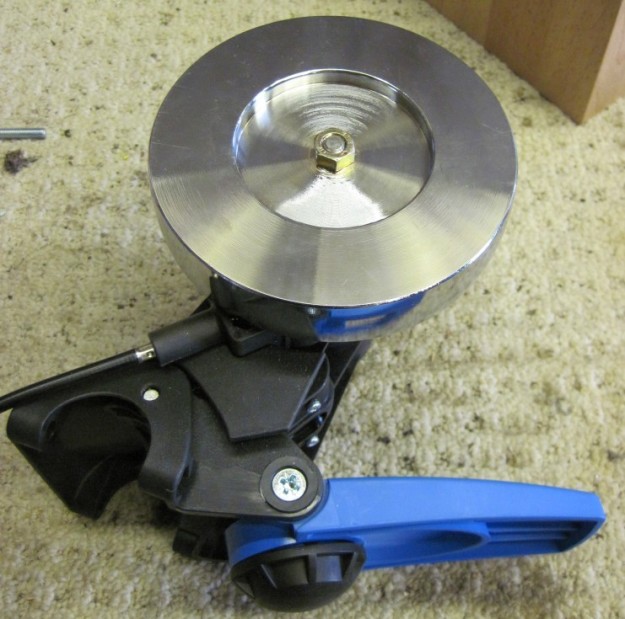
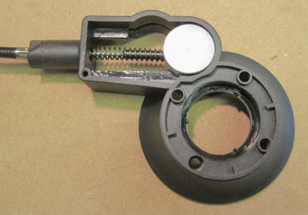
In order to start experimenting with electromagnetic resistance control, I first needed to remove the original cable operated magnet assembly from the resistance unit.
The first step was to remove the resistance unit from the frame, by undoing a pair of hex bolts. (Not strictly necessary – but will make the following steps much easier).
Next the black cap can be prised off the flywheel with a small screwdriver, exposing the 13mm retaining nut underneath.
Note: there is not enough exposed thread to make it obvious, but this is a left-handed thread. Fortunately, I had found this out via Google already – else I may have been stuck at this stage for some time ;) The flywheel body needs to be securely held with a strap wrench, or in a large vice, while the nut is turned in a clockwise direction to loosen and remove it (the opposite direction to a standard thread).
 I then supported the flywheel between two blocks of wood, and gave the end of the shaft a tap with a rubber mallet to knock it out of the flywheel… and then a heftier tap, and another… Ok, so this wasn’t moving easily! I then put it on my drill press table, and applied as much pressure as I dared trying to shift it, but still no go.
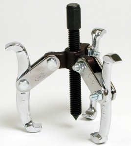
In the end I had to resort to a sharp smack with a lump hammer, which fortunately didn’t damage the threads. As I’ll doubtless be taking the flywheel on & off repeatedly during development, I’ll invest a in gear puller (right) to make future attempts less brutal.
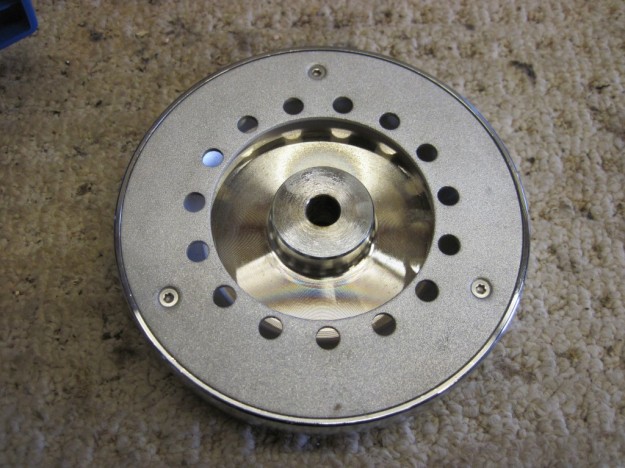
With the flywheel off, you can easily see the non-ferrous disk on the inside. This disk passes through the magnetic field, creating the eddy currents and the resulting opposing magnetic field that results in the braking force.
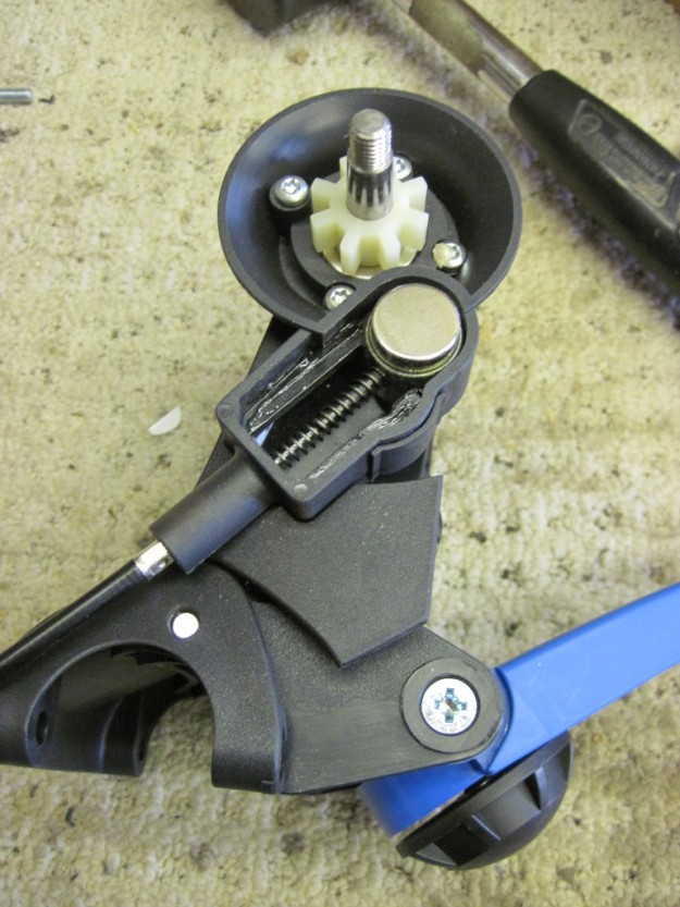
The picture below shows the sliding magnet assembly that sits behind the flywheel. The small plastic collar sits fairly loosely on the shaft and doesn’t appear to serve much purpose. Am assuming it’s there just to create some cooling airflow?
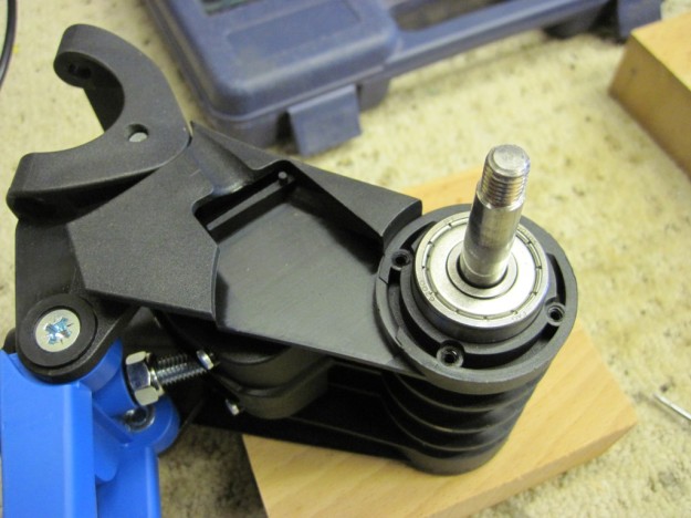
Once the 4 torx screws are removed, the plastic magnet assembly just pulls off the main body, revealing the left hand side bearing.
Is a bit hard to see from the photo, but there’s a lip around the inside of the assembly that holds this bearing in place.
Next up, I’ll replace this assembly with a platform for mounting and experimenting with various electromagnets..
