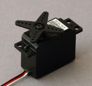
A basic requirement for this project will be to accurately adjust the trainer resistance cable throughout its range of motion. (Time will tell how accurate we can get!). As a starting point, there are probably three viable options for moving the cable – a hobby servo, a DC gear motor with leadscrew, and a stepper motor with leadscrew.
For: Simplest mechanical build, positional adjustment directly from a microcontroller (no driver IC circuitry), reasonable accuracy and resolution.
Against: Will always be pulling against the load, so likely the highest stress on the motor and bearings. Need to convert angular to linear travel.
A standard hobby servo (commonly used in RC planes and cars) provides angular positional control of a movable arm or linkage, commonly over an angle of around 180 degrees, and with a minimum resolution of <1 degree. The torque of hobby servos is rated in kg*cm, so for instance a 4kg*cm servo would be able to move a load of 4kg at a distance of 1cm from the axis of the shaft. In our case we need to produce a maximum load of 5kg, over a travel of 30mm. As a rough estimate, we can get this travel from around 120 degrees rotation, at an arm length of 16mm. This would require a minimum torque of around 7.5kg*cm.
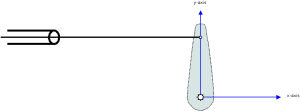 With the cable attached directly to the arm, we also need to calculate the required angular position for a given linear motion along the x-axis. In the diagram to the left – the arm will need to rotate further to achieve the same linear travel as it moves away from the y-axis. Knowing the the total travel along the x-axis, and the proportion required, we can calculate this from the arcsin of a unit circle. (Is worth noting that there will also be some inaccuracy introduced as the point of attachment moves off axis in relation to the cable outer fixing. However, the length of the servo arm is small compared to the distance from the cable mount, so this angle will be quite small and will be ignored for now). These calculations would be greatly simplified by attaching a pulley or wheel to the servo, and running the cable around the outside. Unfortunately the cable is a bit thick for this bend radius, but could be attached to the pulley via a thinner wire.
Option 2 – DC Gear Motor & Le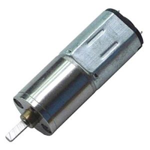 adscrew
For: Using a leadscrew means less strain on the motor (especially when holding a static position)
Against: H bridge or driver IC required, likely to be a more complex mechanical build, unlikely to have built in positional sensing.cover
A DC motor rotates when power is applied, reversing the polarity of the power will reverse the direction of rotation. A DC gear motor is a common form where the output of the motor is transmitted through an integral gearbox before reaching the output shaft.
To achieve linear movement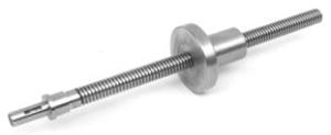 , a leadscrew can be coupled to the motor output shaft, whereby a nut is moved up and down the threaded shaft as it spins. Although this assembly introduces an amount of friction, it does have an advantage that it will tend to be self locking when stationary.
A commercial lead screw has a different type of thread to a standard threaded rod (for reduced friction), but the parts are more expensive, so standard v-threaded rod is sometimes used in small DIY projects.
This complete arrangement of motor and leadscrew is known as a linear actuator and can be bought commercially (greatly simplifying the mechanical build), however in almost all cases, the cost would exceed our entire project budget.
To track the rotation of a DC motor, it is common to use a shaft encoder of some type. These provide a specific number of logic output pulses per rotation. Another alternative would be a linear potentiometer to measure the position of the nut on the leadscrew.
Option 3 – Stepper Motor & Leadscrew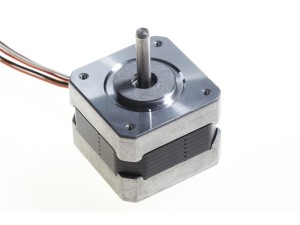
For: Best accuracy, using a lead screw means less strain on the motor (especially when holding a static position)
Against: H bridge or driver IC required, likely to be a more complex mechanical build, most bulk/weight (but not really an issue for this project).
A stepper motor provides positional control of rotation, usually at 1.8 degrees resolution, or 200 steps per revolution. Just as with the DC motor, a lead screw can be coupled to the shaft to achieve linear movement. This solution gives great accuracy, with 200 steps for each pitch of the thread. Again, complete linear stepper assemblies can be bought, and again would almost certainly blow the budget.
First Prototype
Doesn’t get any simpler than this!
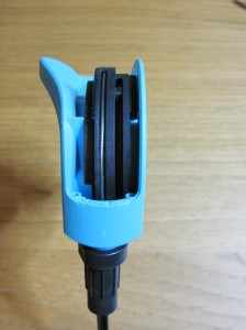
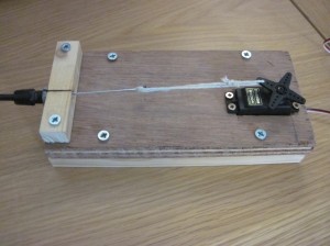 The resistance cable is directly attached to the servo arm, and we can use use a bit of remedial maths to calculate the required arm angle for a given linear position of the cable.
This servo wasn’t powerful enough for a full range of motion (the force on the cable increases as the spring in the resistance unit is compressed), but was sufficient to get things started and verify the maths.
A more powerful servo is in the post, and I have a few DC and stepper motors in my parts drawer, so plenty of scope for more experimentation..
Next post will mostly cover software, microcontrollers, and adding rudimentary device support to Golden Cheetah
